# Seamless Integration in Marine Systems: Beyond the Marketing Promise
Modern vessel electronics fail not from individual component weakness but from poor communication between systems. Your chartplotter, radar, autopilot, and engine monitoring equipment each generate valuable data, yet without proper integration, you’re forced to mentally correlate information across multiple displays while managing your vessel. This cognitive burden increases reaction times during critical moments and masks developing mechanical issues until they become serious problems.
True system integration creates a unified intelligence layer across your vessel’s electronics. When your radar detects a target, an integrated system automatically overlays that contact on your chartplotter, calculates collision risk, and can trigger automated helm response through the autopilot. Engine data flows directly to alarm systems that recognize patterns indicating impending failure. Navigation information feeds fuel consumption calculations that adjust route planning in real time.
The difference between genuine integration and basic connectivity is profound. Connecting devices through a network allows them to share data. Integration requires those systems to interpret, correlate, and act on information from multiple sources simultaneously. A connected system displays engine temperature on your multifunction display. An integrated system compares that temperature against load conditions, ambient water temperature, historical performance data, and manufacturer specifications, then alerts you to anomalies before gauge readings reach critical levels.
This distinction matters because vessel electronics represent substantial investments, and their configuration determines whether you gain operational intelligence or simply accumulate more screens to monitor. Professional integration engineering considers data architecture, protocol compatibility, update synchronization, and failure mode behavior. The result transforms individual instruments into a cohesive system that enhances situational awareness, improves safety margins, and extends equipment lifespan through early fault detection.
Understanding what proper integration delivers, how marine engineers achieve it, and how to evaluate integration quality protects your investment and your vessel’s operational capability.
What Seamless Integration Actually Means in Marine Systems
The marine industry throws around “seamless integration” with alarming frequency, but the technical reality differs substantially from the marketing hype. True integration in marine systems means establishing unified communication protocols that allow disparate electronics to exchange data bidirectionally, coordinate their responses, and function as a single cohesive unit rather than a collection of standalone devices wired to the same power source.
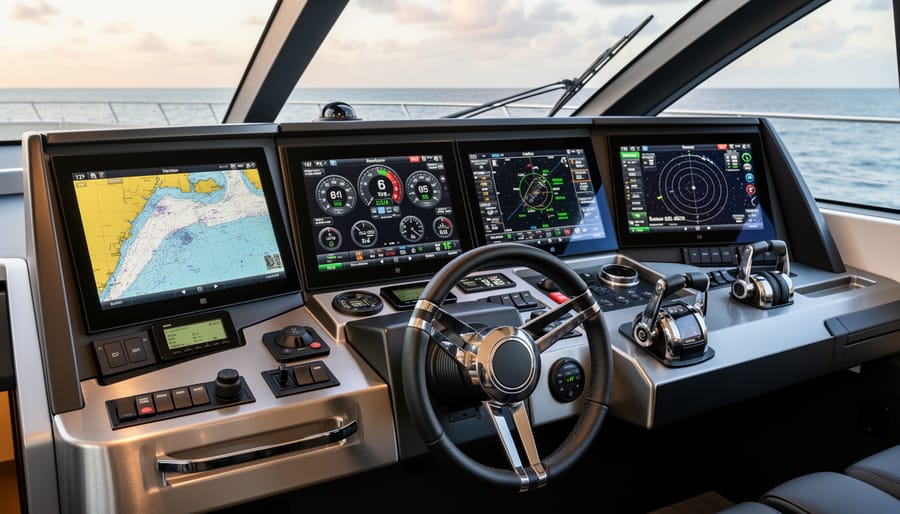
At the core of genuine integration lies standardized communication architecture. Modern integrated systems rely on specific protocols and data structures that enable real-time information sharing across all connected components:
- NMEA Protocols
- Standardized communication languages (particularly NMEA 0183 and NMEA 2000) that define how marine electronics format and transmit navigation, sensor, and control data between devices.
- CAN Bus Systems
- Controller Area Network architecture borrowed from automotive engineering that enables multiple devices to communicate on a single backbone without a central computer, reducing wiring complexity while increasing data reliability.
- Data Interoperability
- The capability of different manufacturers’ equipment to accurately interpret and utilize data originating from other devices, regardless of brand or model.
- System Architecture
- The physical and logical framework that determines how components connect, communicate priorities, handle data conflicts, and maintain operational integrity when individual elements fail.
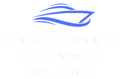
Consider a practical example. When your radar detects a target, an integrated system doesn’t just display a blip on one screen. The radar data flows through NMEA 2000 standards to your chartplotter, which overlays the target on your navigation display. Your autopilot receives the same data and can execute collision avoidance maneuvers if programmed. The AIS transponder cross-references the radar contact with transmitted vessel information. Your alarm system monitors the closing rate and triggers warnings based on preset parameters.
This coordinated response happens automatically, in milliseconds, without operator intervention. That’s the technical definition of integration.
Contrast this with simply connecting multiple devices to a common display through basic data sharing. You might see information from various sources on one screen, but the devices don’t communicate with each other, coordinate their functions, or provide unified control. The autopilot can’t respond to radar data. The chartplotter can’t overlay AIS information with depth sounder readings to predict safe passage.
Genuine integration requires compatible hardware, properly configured software, and correct physical installation that maintains signal integrity throughout the network. The difference between connected devices and integrated systems determines whether your electronics enhance situational awareness and safety or simply clutter your helm with redundant information.
The Real-World Impact of Poor Integration
Poor integration between marine electronics creates problems that extend far beyond minor inconveniences. These failures compromise vessel safety, reduce operational efficiency, and can lead to costly navigational errors.
Consider a common scenario: a vessel equipped with multiple chartplotters and navigation displays, each receiving GPS data from different sources. Without proper integration, these systems can display conflicting positions. One multifunction display shows the vessel 50 feet north of its actual location while another shows it 30 feet south. The radar overlay doesn’t align with the chart beneath it. The helmsman faces an impossible decision about which system to trust, particularly in restricted waters where accuracy matters most.
Temperature and depth sensor conflicts present equally serious risks. An engine monitoring system might pull coolant temperature data from one sensor while the alarm system references another. If these sensors aren’t calibrated together or if their data isn’t properly reconciled through integrated protocols, you could receive a high-temperature alarm while the main display shows normal readings. This ambiguity forces crew members to spend critical minutes troubleshooting instrumentation instead of addressing potential mechanical failures.
Autopilot systems demonstrate integration failures with particular clarity. When heading sensors, GPS units, and compass systems aren’t fully integrated, the autopilot receives competing directional information. The result ranges from inefficient steering that wastes fuel to dangerous course deviations. A fishing vessel working near offshore structures or a yacht navigating a crowded harbor can’t afford these errors.
Redundant displays showing different information create another layer of risk. If your helm station, flybridge, and navigation console each present unique data from the same sensor network, someone will make decisions based on outdated or incorrectly processed information. During equipment failures or emergency situations, this confusion multiplies exponentially.
The operational costs compound over time. Crews waste hours reconciling conflicting data, performing unnecessary maintenance on sensors that appear faulty but simply aren’t communicating properly, and second-guessing instrumentation they should trust implicitly. Professional mariners recognize these symptoms immediately because they’ve seen integration failures compromise safety margins that shouldn’t be negotiable.
Core Components of a Seamlessly Integrated Marine System
Navigation and Autopilot Coordination
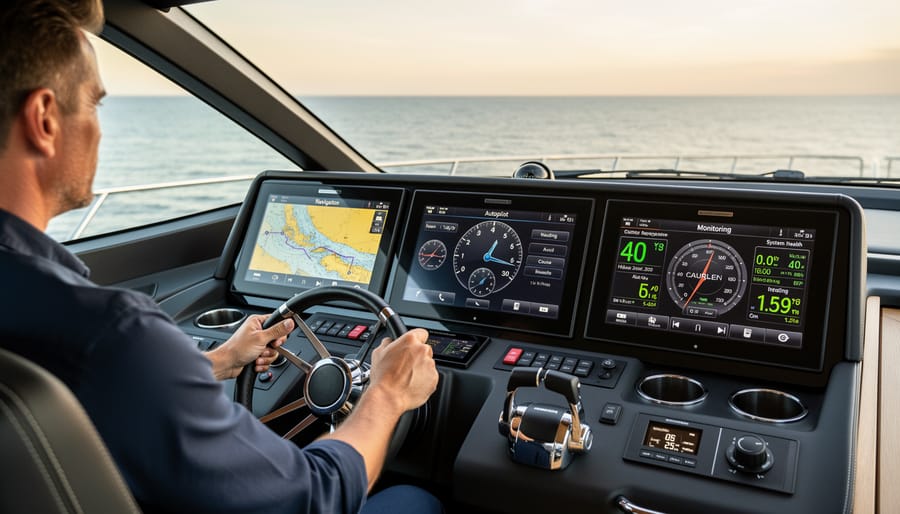
Modern vessel navigation achieves true integration when GPS, chartplotters, radar, AIS, and autopilot systems function as a unified intelligence network rather than isolated instruments. This coordination transforms raw positional data into actionable vessel control.
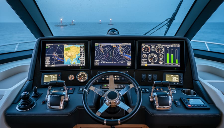
At the core sits NMEA 2000 or similar protocols that allow continuous data exchange between components. Your GPS provides precise position and speed over ground. The chartplotter overlays this onto electronic charts while receiving radar returns and AIS targets from their respective systems. Instead of forcing the helmsman to mentally correlate information from separate displays, integrated systems present a single consolidated picture showing your vessel’s position, surrounding traffic, weather cells, and navigational hazards simultaneously.
The autopilot benefits most dramatically from this data sharing. Rather than simply maintaining a compass heading, modern integrated autopilots receive GPS course data, cross-track error corrections from the chartplotter, and collision avoidance alerts from radar and AIS. The system makes micro-adjustments accounting for current set and drift, automatically compensates for course deviations, and can even execute waypoint navigation without manual intervention.
This coordination delivers measurable safety improvements. When AIS detects a vessel on a collision course, the integrated system calculates closest point of approach, triggers visual and audible alarms, and can disengage autopilot control to alert the helmsman. Radar guard zones work similarly, creating automated watch zones that surpass human vigilance during extended passages.
The difference between connected devices and genuine integration becomes clear in these scenarios. Connected systems display the same data separately. Integrated systems synthesize multiple inputs to generate intelligence that exceeds the sum of individual components, creating situational awareness that directly improves navigation decisions and vessel safety.
Power Systems and Load Management
Effective power management aboard modern vessels requires more than installing individual components. True integration creates a unified energy ecosystem where solar arrays, battery banks, generators, and shore power operate as coordinated partners rather than isolated systems. The difference becomes apparent during cloud cover transitions: properly integrated systems automatically adjust generator startup thresholds based on battery state-of-charge, forecasted consumption patterns, and available solar output. This prevents the wasteful cycling of diesel generators and extends battery lifespan.
Load monitoring plays a critical role in this coordination. Real-time consumption data allows the system to prioritize essential services during low-availability periods, automatically shedding non-critical loads before battery reserves reach critical levels. Advanced implementations can even predict power requirements based on time-of-day patterns and operational profiles, pre-warming generators during anticipated demand spikes.
The challenge lies in creating communication pathways between components from different manufacturers. Standardized protocols like NMEA 2000 and Modbus enable this dialogue, but proper configuration requires understanding each device’s capabilities and limitations. Without this foundation, you’re left manually managing what should be automatic decisions, sacrificing both efficiency and reliability. Integration transforms reactive power management into proactive energy optimization.
Engine and Mechanical System Monitoring
Modern vessels generate enormous volumes of operational data every second, yet this information becomes valuable only when unified into actionable intelligence. True integration of engine and mechanical systems transforms isolated sensor readings into comprehensive performance visibility.
Engine monitoring integration pulls data directly from critical components: oil pressure sensors, coolant temperature gauges, fuel flow meters, vibration monitors, and exhaust gas analyzers. Rather than requiring operators to check individual instruments scattered across the engine room, integrated systems consolidate these readings into centralized displays accessible from the bridge or remote monitoring stations.
The technical foundation requires standardized communication protocols. NMEA 2000 networks, J1939 interfaces, and Modbus connections enable different manufacturers’ equipment to share data without proprietary barriers. This protocol compatibility ensures that your Caterpillar engine communicates effectively with your fuel management system and battery monitors, regardless of brand.
Real-time alerts represent integration’s most immediate safety benefit. When fuel pressure drops below operational thresholds or bearing temperatures climb dangerously high, integrated systems trigger instant notifications across multiple stations simultaneously. Operators receive context-rich warnings that include trending data, not just isolated alarm conditions.
The commitment to excellence in system integration extends beyond installation. Proper calibration ensures sensor accuracy, while regular validation confirms data integrity throughout the network. This attention to technical precision separates professional integration from simple device connectivity.
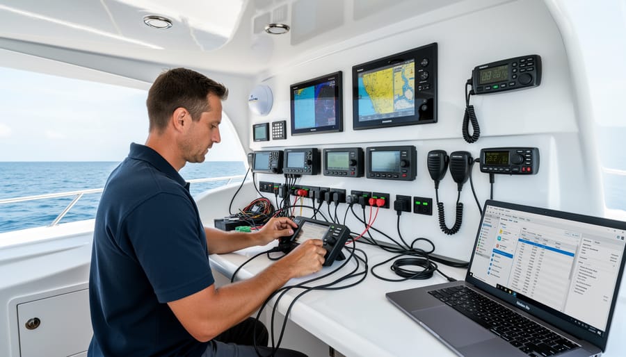
The Engineering Process Behind True Integration
Designing a truly integrated marine electronics system begins long before the first cable runs through a bulkhead. Professional integrators start with comprehensive system architecture planning, mapping every component, data pathway, and power requirement across the vessel. This blueprint identifies which protocols each device speaks, NMEA 2000 backbone topology, Ethernet network architecture, and potential bottlenecks before they become installation-day problems.
The physical installation demands meticulous attention to cable management and signal integrity. High-speed data networks require proper termination and shielding. NMEA 2000 installations need correctly calculated backbone lengths, appropriate drop cables, and precise termination resistors at each end. Professional installers understand that a radar system positioned too close to a compass can introduce deviation, or that sharing power circuits between sensitive electronics and high-draw equipment invites voltage fluctuations and system resets.
Network configuration separates competent installations from exceptional ones. Each device receives appropriate IP addressing within the vessel’s network architecture. VLANs may segregate critical navigation systems from entertainment networks. Routing tables ensure data flows efficiently between systems without creating broadcast storms that bog down the entire network. Quality of Service settings prioritize navigation-critical data packets over less time-sensitive information.
The programming phase brings the architecture to life. Radar overlay settings align precisely with chartplotter displays. AIS targets appear with proper symbology and identification data. Autopilot systems receive correctly formatted GPS position data, heading information from gyrocompasses or electronic compasses, and rudder feedback sensors. Depth sounders, wind instruments, and speed logs feed their data to multiple displays simultaneously without conflict.
Integration extends to alarm management across the platform. Engine monitoring systems communicate with central displays. Bilge alarms trigger notifications on navigation screens. Low-voltage warnings reach appropriate stations. This unified approach ensures no critical alert goes unnoticed because it appeared only on a single, unmonitored display.
Validation testing proves the system performs as designed. Professionals verify data accuracy across all displays, checking that GPS coordinates, heading, speed, and depth match precisely on every screen. They simulate fault conditions to confirm backup systems engage properly. Network stress tests ensure stable performance under maximum data load. Real-world operational testing under various conditions reveals integration issues that bench testing might miss.
The technical expertise required spans multiple disciplines. Integrators need deep knowledge of marine electronics protocols, networking fundamentals, power systems, and vessel dynamics. They understand how different manufacturers implement standards and where compatibility challenges lurk. They recognize that integration isn’t about connecting devices, but about creating a cohesive system where the whole exceeds the sum of its parts.
Documentation completes the process. Comprehensive system diagrams, network maps, device configurations, and calibration records enable future troubleshooting and upgrades. Without proper documentation, even expertly integrated systems become black boxes when modifications become necessary.
Common Integration Challenges and Professional Solutions
Even with the best planning, marine integration projects encounter predictable obstacles. Understanding these challenges and their professional solutions separates successful implementations from costly failures.
Legacy equipment remains one of the most frequent complications. Older chartplotters, autopilots, and engine monitoring systems often lack modern communication protocols, creating data silos within your vessel’s network. The symptoms appear subtle at first: your new multifunction display can’t retrieve waypoints from your existing GPS, or engine data won’t populate on upgraded screens. Professional integrators address this through protocol converters and gateway devices that translate between NMEA 0183, NMEA 2000, and proprietary formats. The investment in these bridges preserves your existing equipment’s value while enabling true data sharing across all systems.
Manufacturer-specific protocols present another substantial hurdle. Major electronics brands frequently implement proprietary extensions to standard protocols, limiting interoperability even among otherwise compatible devices. You’ll notice this when certain data fields remain blank or advanced features only work within single-brand ecosystems. Expert integrators maintain current certification across multiple manufacturers, understanding the nuances of each system’s implementation. They configure custom sentences and parameter groups that enable cross-brand communication without sacrificing functionality.
| Challenge | Common Symptoms | Professional Solution |
|---|---|---|
| Legacy Equipment Compatibility | Missing data on displays, isolated systems, duplicate sensors required | Protocol converters, gateway devices, strategic replacement planning |
| Proprietary Protocols | Incomplete data fields, single-brand limitations, feature lockouts | Manufacturer certification, custom PGN configuration, middleware solutions |
| Physical Space Constraints | Cable congestion, inadequate ventilation, difficult service access | Modular backbone design, vertical mounting solutions, documented cable management |
| Electrical Interference | GPS drift, radar ghost targets, autopilot instability, VHF static | Proper grounding schemes, cable separation protocols, shielded installations |
Physical space constraints compound as vessel systems grow more complex. Modern boats carry exponentially more electronics than designs from even a decade ago, yet console and cabinet space hasn’t expanded proportionally. Professional installers employ modular backbone architectures that consolidate connections while maintaining service accessibility. They plan three-dimensional routing that accounts for thermal management, using vertical mounting planes and distributed junction points rather than cramming everything into a single overcrowded cabinet.
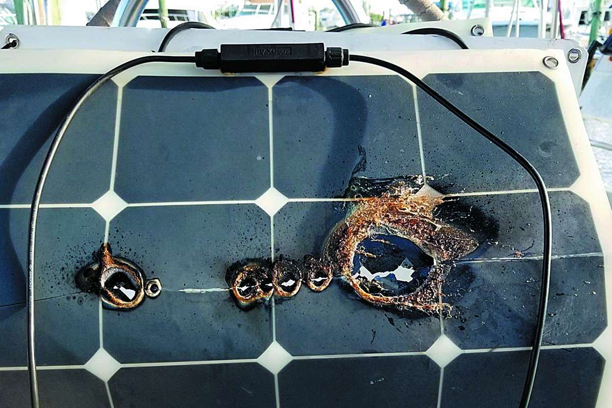
Electrical interference destroys integration reliability. Radio frequency noise from poorly grounded systems creates GPS position errors, phantom radar targets, and erratic autopilot behavior. The VHF crackles during engine operation. These symptoms point to fundamental electrical design flaws rather than equipment defects. Professionals implement proper grounding schemes that separate digital, analog, and RF grounds while maintaining safety bonding. They route power and data cables with appropriate separation distances, use twisted-pair and shielded cables where specifications demand, and install ferrite suppressors strategically rather than haphazardly.
Each challenge requires specific expertise developed through years of troubleshooting actual installations. Your commitment to excellence in marine electronics begins with recognizing these obstacles and engaging professionals equipped to overcome them systematically.
Measuring Integration Success: Performance Indicators That Matter
True marine electronics integration extends beyond basic connectivity. You need measurable benchmarks to separate genuine system performance from marketing claims. Here’s how to evaluate whether your vessel’s electronics actually work as an integrated whole.
Start with data latency, the time between sensor input and display output. In properly integrated systems, radar targets should appear on your multifunction display within 100-200 milliseconds of detection. GPS position updates must flow to autopilot, chartplotter, and AIS transponder simultaneously without perceptible delay. If you notice a lag between changing course and seeing that reflected across all displays, your integration has failed. Test this by making sharp turns and watching how quickly all connected displays respond.
System response times reveal integration quality under load. A well-integrated network maintains consistent performance when multiple applications run concurrently. Pull up radar overlay, sonar bottom imaging, and AIS targets simultaneously on your main display. The system shouldn’t slow down or drop frames. If response degrades when adding functions, you’re dealing with poor network architecture or inadequate processing power, not true integration.
Cross-platform functionality demands that data flows freely between manufacturers’ equipment. Your Garmin chartplotter should display Furuno radar without conversion delays. Raymarine autopilot must accept course changes from any connected MFD. Create test scenarios: set a waypoint on one display and verify it appears instantly on all others. Change autopilot mode from different control points. Each function should work identically regardless of entry point.
User interface consistency matters more than many realize. Integrated systems present unified control logic across devices. Touch targets should be similarly sized, menu structures logically parallel, and terminology consistent. If you must learn entirely different operational concepts for each component, the integration exists only at the hardware level.
Reliability metrics provide the ultimate test. Track system uptime over extended periods. Count how often you need to reboot components or reset network connections. Professional integration delivers months of continuous operation without intervention. Document any failures, noting whether problems cascade through the network or remain isolated. True integration includes fault tolerance that prevents single-point failures from crippling your entire electronics suite.
Measure network bandwidth utilization during peak operations. Your NMEA 2000 or Ethernet backbone should operate below 70% capacity even when every device transmits simultaneously. Higher utilization indicates approaching saturation, which will cause the data delays and dropouts that destroy integration effectiveness.
Future-Proofing Your Integrated Marine Electronics
Marine electronics evolve at breakneck speed, yet vessel infrastructure remains in place for decades. This mismatch creates a critical challenge: how do you build integrated systems today that won’t become obsolete bottlenecks tomorrow? The answer lies in architectural decisions made during initial installation, not in the sophistication of individual components.
Modular architecture forms the foundation of adaptable integration. Rather than hardwiring proprietary connections between devices, structure your network around open standards like NMEA 2000 and Ethernet backbones. These protocols have proven longevity and manufacturer independence. A properly designed backbone with excess capacity accommodates new sensors, displays, and processors without rewiring existing installations. Install more network drops than you currently need. That extra expense now prevents invasive upgrades later.
Power infrastructure requires similar foresight. Today’s 12-volt systems may seem adequate, but higher-resolution radar, thermal cameras, and advanced autopilot computers draw significantly more amperage than legacy equipment. Design your electrical distribution with 30-40% overhead capacity. Include dedicated circuits for high-draw devices rather than daisy-chaining power connections. Document every circuit meticulously because future installers will need to understand your architecture.
Standardized data protocols protect your investment better than any single manufacturer’s ecosystem. Proprietary systems lock you into one vendor’s upgrade path and pricing structure. Open protocols let you mix best-in-class components as technology advances. Your chart plotter may become outdated in five years, but the radar, depth sounder, and AIS transponder feeding it data through standardized connections remain viable.
Plan specific upgrade pathways during initial installation. Run conduit between logical equipment locations even if you don’t immediately need the connections. Reserve panel space for future displays and processors. Choose gateway devices that translate between protocol generations, ensuring legacy sensors remain compatible with next-generation processors.
The vessels with the longest-lasting integrated systems aren’t those with the most expensive equipment today. They’re the ones built on flexible architecture that accepts technological evolution without requiring complete reconstruction.
True integration across marine electronics and vessel systems delivers more than operational convenience. It fundamentally determines whether your vessel operates safely under demanding conditions, whether critical systems respond when seconds matter, and whether your investment in technology delivers reliable performance over years of service.
The difference between genuine integration and simply mounting equipment on a panel becomes apparent during the first equipment failure or challenging navigation scenario. Properly integrated systems provide redundancy pathways, intelligent fault management, and coordinated responses that isolated components cannot achieve. When your autopilot, radar, AIS, and navigation systems communicate through verified protocols with fail-safe architectures, you gain capabilities that transform vessel operation.
Achieving this level of integration demands specialized expertise that extends far beyond installation skills. Marine electronics engineers must understand signal integrity across different protocols, power management under varying loads, electromagnetic compatibility in confined spaces, and the interaction between mechanical, electrical, and software systems. They design integration architectures that account for vessel-specific requirements, operational profiles, and future expansion needs.
The piecemeal approach carries hidden costs that extend beyond initial savings. Incompatible firmware versions, grounding conflicts, inadequate power distribution, and communication bottlenecks create ongoing reliability problems. Each added component increases complexity without necessarily improving capability. Professional integration establishes coherent system architecture from the outset, eliminating these conflicts while maximizing the value of every installed component.
Your vessel deserves an integration strategy built on engineering principles rather than convenience. The expertise required to design, implement, and validate truly integrated marine systems represents an investment in safety, reliability, and operational capability that pays dividends throughout your vessel’s service life. Choose partners who understand that integration excellence requires commitment to technical precision at every level.

Leave a Reply